SEVEN SEGMENT DISPLAY INTERFACING WITH ARM
A seven segment display is the most basic electronic display device.It demonstrates the principle of interfacing Seven segment with ARM LPC2148. The seven segments can display one digit at a time.
Synopsis

A seven segment display is the most basic electronic display device. A seven segment consists of eight LEDs which are aligned in a manner so as to display digits from 0 to 9 and some letters when proper combination of LED is switched on. The most common configuration has an array of eight LEDs arranged in a special pattern to display these digits. They are laid out as a squared-off figure ‘8’. It demonstrates the principle of interfacing Seven segment with ARM LPC2148. The seven segments can display one digit at a time. Thus the no. of segments used depends on the no. of digits in the number to be displayed.

Description

ARM is one of the major options available for embedded system developer. LPC2148 is the widely used IC from ARM-7 family. It is manufactured by Philips and it is pre-loaded with many inbuilt peripherals making it more efficient and a reliable option for the beginners as well as high end application developer.

ARM is a family of instruction set architectures for computer processors based on a reduced instruction set computing (RISC) architecture developed by British company ARM Holdings .A RISC-based computer design approach means ARM processors require significantly fewer transistors than typical processors in average computers. This approach reduces costs, heat and power use. These are desirable traits for light, portable, battery-powered devices including smartphones, laptops, tablet and notepad computers and other embedded systems. A simpler design facilitates more efficient multi-core CPUs and higher core counts at lower cost, providing higher processing power and improved energy efficiency for servers and supercomputers.


The ARM LPC2148 features are as follows:

1. Architecture: ARM v4T

2. Processor: ARM7-TDMI-S

3. Instructions: 32-bit ARM and 16-bit Thumb

4. Debug support: RT Embedded ICE, Embedded Trace interface

5. Static RAM: 32 KB

6. (On-chip)Additional: 8 KB for USB DMA

7. Flash Program: 512 KB

8. Mem.(On-chip)Programming: ISP/IAP via on-chip boot-loader program

9. GPIO No. of pins: up to 45 (fast GPIO lines, 5V tolerant), Configurable to fast GPIO

10. External Interrupts: Four; No. of pins: Nine

The ARM LPC2148 has two ports Port 0 and Port 1 respectively each port contains 32-bits for I/O operations. The Port 0 has 32-bit of I/O pins for individual directions and Port 1 has 32-bits of I/O pins for bidirectional purpose. It has two timers of each 32-bit. It has capable to storing 128-bit memory for interfacing.

Over the last few years, the ARM architecture has become the most pervasive 32-bitarchitecture in the world, with wide range of ICs available from various IC manufacturers. ARM processors are embedded in products ranging from cell/mobile phones to automotive braking systems. A worldwide community of ARM partners and third-party vendors has developed among semiconductor and product design companies, including hardware engineers, system designers, and software developers.

seven segment display consists of seven LEDs (hence its name) arranged in a rectangular fashion as shown. Each of the seven LEDs is called a segment because when illuminated the segment forms part of a numerical digit (both Decimal and Hex) to be displayed. An additional 8th LED is sometimes used within the same package thus allowing the indication of a decimal point, (DP) when two or more 7-segment displays are connected together to display numbers greater than ten.

Each one of the seven LEDs in the display is given a positional segment with one of its connection pins being brought straight out of the rectangular plastic package. These individually LED pins are labelled from a through to g representing each individual LED. The other LED pins are connected together and wired to form common pin.


So by forward biasing the appropriate pins of the LED segments in a particular order, some segments will be light and others will be dark allowing the desired character pattern of the number to be generated on the display. This then allows us to display each of the ten decimal digits 0 through to 9 on the same 7-segment display. The displays common pin is generally used to identify which type of 7-segment display it is. As each LED has two connecting pins, one called the “Anode” and the other called the “Cathode”.

There are two types of seven segments:

1. Common Cathode

2. Common Anode

1) Common Cathode: In the common cathode display, all the cathode connections of the LED segments are joined together to logic 0 or ground. The individual segments are illuminated by application of a HIGH, or logic 1 signal via a current limiting resistor to forward bias the individual Anode terminals (a-g).


2) Common Anode: In the common anode display, all the anode connections of the LED segments are joined together to logic “1”. The individual segments are illuminated by applying a ground, logic “0” or “LOW” signal via a suitable current limiting resistor to the Cathode of the particular segment (a-g).


In a simple LED package common cathode SSD, there has 10 pin out of which 2 is ground and rest is LED segments . Particular LED segment is glow(ON) by giving logic ‘1’ to it and rests at logic ‘0’. So we need to program this 8 pin to display our number on SSD. In following table, we convert this 8 pin’s 8 bit binary data into hex code and shows the hex code of displaying digits below.

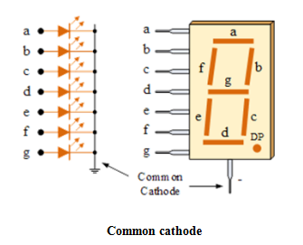
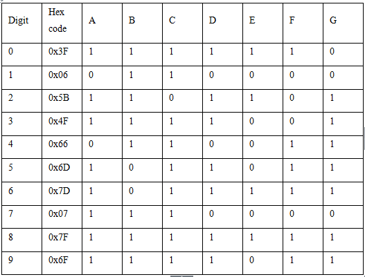
Common Cathode configuration:


In common anode LED segment is glow(ON) by giving logic ‘0’ to it and rests at logic ‘1’.

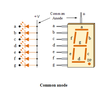
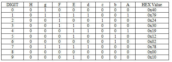
Common Anode configuration:


Seven segment display (SSD), or seven-segment indicator, is a form of electronic display device for displaying decimal numerals that is an alternative to the more complex dot matrix displays.

Applications

• Digital clocks

• Pricing menu at petrol pump

• In metros

• Electronics meters

Proteus design for Seven Segment interfacing with ARM


Orcad design for Seven Segment interfacing with ARM


Seven Segment interfacing with ARM

/*  Name     : main.c
 *  Purpose  : Source code for SEVEN SEGMENT Interfacing with ARM LPC1248.
 *  Author   : Gemicates
 *  Date     : 2018-11-01
 *  Website  : www.gemicates.org
 *  Revision : None
 */
#include<lpc21xx.h> 								// header file for LPC21XX series

void delay(int time) 								// delay function declaration
{										// This function produces a delay in msec
int i,j;
for(i=0;i<time;i++)
{
for(j=0;j<i;j++);
}
}

int main()								        // main function
{
int i,a[]={0x40,0x79,0x24,0x30,0x19,0x12,0x02,0x78,0x00,0x10,0x00,0x10};        // assign the array values as the hexadecimal no. of common anode to display the digits
PINSEL0=0x00000000;							        // select PORT0 as GPIO mode
IO0DIR=0xFFFFFFFF;							        // make PORT0 pin as Output mode 
while(1)								        // Repeat(loop) forever
{ 
for(i=0;i<10;i++)							        // This loop excutes for 9 times
{
IO0SET=a[i]; 								        // Set the first 8 PORT0 pins
delay(1000); 								        // hault for sometime
IO0CLR=a[i];								        // clear the first 8 PORT0 pins
}
}
return 0;								        // return back to main function
}
 

Error message here!

Show Error message here!


Forgot your password?

Error message here!

Send OTP

Error message here!

Show Error message here!


Lost your password? Please enter your email address. You will receive a password you Need.

Send Error message here!


Back to log-in

Close